


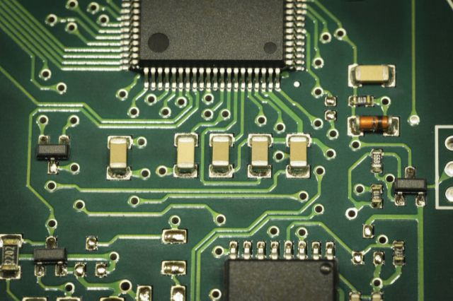
Reflow soldering is one of the most commonly used methods for assembling printed circuit boards (PCBs), especially in surface mount technology (SMT). It’s widely used for its consistency and precision, making it a reliable way to secure components to the board at scale.
In this guide, we’ll break down what reflow soldering is, how it works, the key stages involved and why it’s such an essential process in electronics manufacturing.
What Is Reflow Soldering?
Reflow soldering is a process used to attach surface mount components to a PCB by melting solder paste. The paste, which is a mixture of powdered solder and flux, is first applied to the board. Components are then placed on top, and the entire assembly is heated in a controlled way until the solder melts and forms strong connections.
Once cooled, the solder solidifies, securing the components in place.
This method is often used in large scale production because it is efficient, it delivers consistent results and is typically far more accurate than manual soldering.
How Does Reflow Soldering Work?
Reflow soldering is all about controlled heating and cooling. The process follows a carefully designed temperature profile that ensures the solder melts properly without damaging the components or the board.
Here’s how it works step by step:
- Solder Paste Application
The process begins with applying solder paste to the PCB using a stencil. The stencil ensures the paste is deposited only on the pads where components will be placed.
Accuracy at this stage is crucial. Too much or too little solder paste can lead to defects such as bridging, insufficient joints or tombstoning.
- Component Placement
Once the solder paste is applied, components are placed onto the board using pick and place machines. These machines position components with high precision, aligning them with the solder covered pads.
The tackiness of the solder paste helps hold components in place before the heating process begins.
- Reflow Oven Process
The assembled PCB is then passed through a reflow oven. This is where the actual soldering happens.
The oven heats the board in stages, following a specific temperature profile. This profile is carefully controlled to make sure the solder joints are reliable and to avoid thermal damage.
The Reflow Soldering Temperature Profile
A typical reflow soldering profile is divided into four main stages: Preheat, thermal soak, reflow and cooling. Let’s take a look at each stage…
The Preheat Stage
During the preheat stage, the temperature of the PCB is gradually increased. This helps to activate the flux and remove and moisture. Starting with a controlled ramp-up is important to avoid damaging sensitive components.
The Thermal Soak Stage
In the soak stage, the temperature is held steady for a short period of time. This allows the entire board to reach one specific temperature and ensures the flux fully activates.
This stage also helps reduce temperature differences between large and small components, which improves the overall quality of the solder joints.
The Reflow Stage
This is where the solder paste actually melts. The temperature is raised above the solder’s melting point, allowing it to flow and form connections between the component leads and PCB pads.
This stage must be carefully controlled to avoid issues such as cold joints, head-in-pillow defects or general overheating.
The Cooling Stage
After reflow, the board is gradually cooled down. The solder solidifies during this stage, forming strong, reliable joints.
Controlling the cooling is just as important as the heating stages because cooling the board too quickly or too slowly can affect the strength and structure of the solder joints.
What are the Different Types of Reflow Ovens?
When it comes to reflow soldering, there are several types of reflow ovens available and each is suited to different production needs. Here are some examples:
Convection Reflow Ovens – These are the most commonly used. They circulate hot air to heat the PCB evenly, offering consistent and reliable results.
Infrared (IR) Reflow Ovens – These ovens use infrared radiation to heat components directly. While they can be effective, they are less common due to the risk of uneven heating, especially with mixed component sizes.
Vapour Phase Reflow – This method uses a heated vapour to transfer heat to the PCB. It provides very uniform heating and eliminates any risk of overheating which makes it ideal for sensitive or complex assemblies.
What are the Advantages of Reflow Soldering?
There are many advantages to reflow soldering with some of the main ones being that is it incredibly precise and highly reliable. It is perfect for complex and densely populated PCB’s and excellent for working with large scale production. There is of course the benefit of reduced human error and the results are consistent, strong solder joints.
These advantages make it the preferred method for SMT assembly across many industries.
Common Defects in Reflow Soldering and How to Spot Them
Like any manufacturing process, reflow soldering can also present challenges if not it is not properly controlled.
Some common defects that can occur are solder bridging, cold joints, tombstoning and voiding. Most of these issues can be traced back to problems with the solder paste application, component placement or temperature profiling.
If you’re working with reflow soldering, certification in IPC J-STD-001 and IPC-A-610 covers you for both sides of the process. IPC J-STD-001 focuses on how soldering should be carried out, helping you understand the requirements behind a controlled and reliable reflow process, from materials to workmanship. IPC-A-610 then complements this by defining what acceptable solder joints look like, so you can confidently inspect and verify quality.
Together, they ensure that you’re running the process correctly and also consistently producing assemblies that meet industry standards without any defects.
How Many Times Can You Reflow a PCB?
A PCB can usually go through the reflow process two to three times without causing any damage, as long as the correct temperature profile is used and the components are rated for multiple heat cycles.
This typically covers standard assembly processes such as double-sided PCB assembly, where the board is reflowed once for each side. However, each additional reflow cycle increases the risk of thermal stress on both the components and the board itself.
Too many reflow cycles can cause issues such as warping or delamination of the PCB, damage to components and solder joints or general degradation of the components.
Manufacturers will often specify the maximum number of reflow cycles for their components and these guidelines should always be followed.
Final Thoughts on Reflow Soldering
Reflow soldering might seem like a highly technical process, but when you break it down it is all about control. Control of temperature, timing and materials all come together to create strong, reliable connections on a PCB.
Understanding how it works is valuable whether you’re involved in electronics manufacturing, quality inspection or simply looking to deepen your technical knowledge.
If you’re looking to improve your soldering, inspection or rework skills, then get in touch with our team at The Electronics Group today to see how our training courses can help.